


Vaporizer Operating Principles
INDUSTRIAL GAS, PETROCHEMICAL, ENERGY SECTOR AND CRYOGENIC VAPORIZERS AND TRIM HEATERS OPERATING PRINCIPLES REVIEW
AMBIENT AIR VAPORIZERS
NATURAL DRAFT
Incryo Systems manufactures a comprehensive range of Cryogenic and Industrial gas ambient air vaporizers for the Industrial Gas, Petrochemical and Energy sector industries. Incryo Systems designs its vaporizers in the USA and manufactures and distributes vaporizers globally from its comprehensive manufacturing facility in India.
The performance of ambient air vaporizers, which use the relative “heat” of the atmosphere to derive the energy necessary for the vaporization of the liquid cryogen, is subject to many factors. These include flow rate, duty cycle, ambient temperature, relative humidity, freeze period, altitude, wind, solar radiation, operating pressure and proximity to adjacent structures. The effects of average solar and wind conditions are not included in quoted ratings. Performance is based on mean ambient conditions of 700F (210C) and 70% relative humidity. Special conditions may vary considerably for a particular application, thereby affecting performance. Ambient vaporizers represent the most cost effective equipment to vaporize or re-gasify liquid cryogens. Once installed there are no operational or maintenance costs. All that is required is regular defrosting of the heat transfer elements.
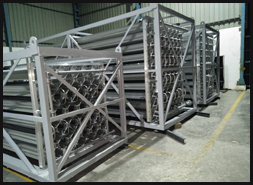
All Incryo Systems vaporizer arrays are weldless. The vaporizer assembly or “array” is assembled using different spaced brackets and clips which are ‘crimped’ to the extrusions. This method of construction provides a high level of structural integrity, but allows the structure to expand and contract whilst in operation, preventing any possible cracking of the structure. Return bends and manifolds necessary to circulate the cryogen within the extrusions are welded in place in accordance with ASME Section IX code. The units may be shipped, handled and installed without additional crating without fear of damage.
LOW PRESSURE, ambient natural draft, part series and parallel configuration
A series of 100% Aluminum construction vaporizers designed specifically for customer station, distribution, project and plant back up applications. All Natural draft vaporizers utilize natural convection as the heat transfer method. The vaporizers comprise a number of individual multi-finned heat transfer elements (extrusions) which are connected in a number of different series and parallel paths providing a design suitable to meet the exact requirements of various applications.
These fins provide a large surface area upon which the “ambient weather conditions” impinge and provide heat energy for vaporization. Because most cryogens are extremely cold (circa 2000C) even the coldest ambient conditions provide a sufficient temperature difference for adequate heat transfer. The energy required to vaporize the required amount of cryogen, is directly proportional to the surface area. In order to provide enough energy from heat transfer, even in the most arduous ambient conditions, sufficient surface area has to be designed into the vaporizer.
Heat transfer elements of varying lengths are available to optimize vaporizers design and minimize the number of vaporizers necessary to meet process demands. Elements are assembled together, if necessary utilizing manifolds to provide single inlet and outlet connections. To provide continuous gas supply multiple units are employed which are ‘switched’ between on line and off line units when operational units are saturated. Manual or automatic switching systems are available.
Connections: Mueller four bolt, ANSI RFWN or SORF or DIN specification flanges.
Standard MAWPs available: 275 psig (19 bar); 450 psig (31 bar); 588 psig (40 bar)
All ISPL vaporizers are designed and manufactured in accordance with the UBC and applicable sections of ANSI A 58.1. Vaporizers may be manufactured in compliance with any global pressure specification, such as ASME; TUV; PED; KGC or ISQL.
LOW PRESSURE ambient natural draft, WIDE SPACED, part series and parallel extrusion configuration
A series of vaporizers designed specifically for customer station and distribution applications for extended operation times. All Natural draft vaporizers utilize convection as the heat transfer method. The vaporizers comprise a number of individual multi-finned heat transfer elements (extrusions) which are connected in a number of different series and parallel paths providing a design suitable to meet the exact requirements of various applications.
These fins provide a large surface area upon which the “ambient weather conditions” impinge and provide heat energy for vaporization. Because most cryogens are extremely cold (circa 2000C) even the coldest ambient condition provides a sufficient temperature difference for adequate heat transfer. The energy required to vaporize the required amount of cryogen, is directly proportional to the surface area. In order to provide enough energy from heat transfer, even in the most arduous ambient conditions, sufficient surface area has to be designed into the vaporizer.
The heat transfer elements are assembled together utilizing an “extra wide” spacing compared to the standard spacing, which assists in preventing ice accumulation which eventually bridges the elements, and fills the interspaces with frost, reducing effective surface area and minimizing air flow through the vaporizer. Extended operating times are possible with extra wide spaced vaporizers with minimal downtime for defrosting.
Heat transfer elements of varying lengths are available to optimize vaporizers design and minimize the number of vaporizers necessary to meet process demands. Elements are assembled together, if necessary utilizing manifolds to provide single inlet and outlet connections.
Connections: Mueller four bolt, ANSI RFWN or SORF or DIN specification flanges.
Standard MAWPs available: 275 psig (19 bar); 450 psig (31 bar); 588 psig (40 bar)
All ISPL vaporizers are designed and manufactured in accordance with the UBC and applicable sections of ANSI A 58.1. Vaporizers may be manufactured in compliance with any global pressure specification, such as ASME; TUV; PED; KGC or ISQL.
LOW PRESSURE ambient natural draft, HYBRID, part series and parallel extrusion configuration
A series of vaporizers designed specifically for customer station, distribution, project and plant back up applications where a physically smaller vaporizer is needed when footprint space is limited but a highly efficient, cost effective serpentine design vaporizer is preferred.
During the operation of a cryogenic vaporizer frost builds up on the fins and during extended periods of time the frost builds up between the fins and effectively “eliminates” the effective surface area required for the vaporization. Eventually when the entire effective surface is covered with frost and is unable to absorb the heat from the atmosphere the vaporizer ceases to be effective and it has to be taken out of service and defrosted.
Heat transfer elements are available with multiple fins. Minimum fin elements are designed to ‘shed’ frost build-up and are considered to “regenerate” their surface area. Maximum fin elements are vulnerable to frost build and lose their effective surface area throughout the vaporizer run time. Hybrid vaporizers have minimum fins in the initial boiling zone where maximum frost occurs, multiple fin elements in the heating zone where moderate frost build up is expected and super multiple fins in the superheating zone of the vaporizer where no frost build is expected.
For design purposes minimum fin elements are considered to have the equivalent surface area as the multi fin elements in the vaporizer because the effective surface area is not lost to frost build up, but regenerates all the time the vaporizer is operational. This concept reduces the number of heat transfer elements in a given vaporizer resulting is a physically smaller, but highly efficient vaporizer.
Heat transfer elements of varying lengths are available to optimize vaporizers design and minimize the number of vaporizers necessary to meet process demands. Elements are assembled together, if necessary utilizing manifolds to provide single inlet and outlet connections. To provide continuous gas supply multiple units are employed which are ‘switched’ between on line and off line units when operational units are saturated. Manual or automatic switching systems are available.
Connections: Mueller four bolt, ANSI RFWN or SORF or DIN specification flanges.
Standard MAWPs available: 275 psig (19 bar); 450 psig (31 bar); 588 psig (40 bar)
All ISPL vaporizers are designed and manufactured in accordance with the UBC and applicable sections of ANSI A 58.1. Vaporizers may be manufactured in compliance with any global pressure specification, such as ASME; TUV; PED; KGC or ISQL.
LOW PRESSURE ambient natural draft, PARAFLOW©, all parallel extrusion configuration
A series of high specification ambient air vaporizers designed in compliance with the Uniform Building Code (UBC), 100 mph wind loads, seismic zone 4 classification, and the ANSI A58.1 code for high flow rate applications and when tighter approach temperatures or longer operating times are required.
In the PARAFLOW® ambient air vaporizer design, all the heat transfer elements (extrusions) are connected together in parallel using inlet and outlet manifolds. This construction technique eliminates the differential thermal gradients between extrusions, the need to compensate for thermal expansion and contraction gradients. All extrusions are at essentially the same temperature at any given vertical elevation. In operation, the PARAFLOW® vaporizer has an entirely different ice accumulation pattern compared to conventional series and parallel (serpentine) designs. This pattern provides a sound mechanical design eliminating the problematic thermal stress characteristics of conventional serpentine designs and results in more efficient heat transfer.
The PARAFLOW vaporizer provides true counter-current-flow between the downward flow of air in natural or forced convection and the upward flow of the cryogen in the vaporizer extrusion. This results in the thermal performance improving by as much as 10-20% compared to conventional designs with the same surface area. The design also provides minimal pressure drop which is generally less than 10% of the inlet pressure.
Ice accumulation during operation occurs in the lower part of the vaporizer, with un-iced extrusions protruding out of the ice pack. This eliminates the large ice pack at the top and one side end of a conventional vaporizer, the cause of vaporizer mechanical strength concerns and the possibility of ice breaking away causing safety concerns. The low level ice build-up also lowers the center of gravity and, therefore, reduces structural strength requirements in meeting the UBC requirements, resulting in reduced vaporizer material cost. The PARAFLOW® vaporizer has specially designed internal configuration which improves convection heat transfer coefficients and eliminates the surging normally accompanying low pressure drop cryogenic vaporizers. A range of models is available with continuous extrusion lengths of up to 12 meters.
Connections: Mueller four bolt, ANSI RFWN or SORF or DIN specification flanges.
Standard MAWPs available: 275 psig (19 bar); 450 psig (31 bar); 588 psig (40 bar)
All ISPL vaporizers are designed and manufactured in accordance with the UBC and applicable sections of ANSI A 58.1. Vaporizers may be manufactured in compliance with any global pressure specification, such as ASME; TUV; PED; KGC or ISQL.
LOW PRESSURE ambient natural draft, PRESSURE BUILDING , part series and parallel extrusion configuration, horizontal of vertical orientation.
A series of vaporizers designed specifically for pressure building applications. Natural draft vaporizers utilize natural convection as the heat transfer medium. The vaporizers comprise a number of individual multi-finned heat transfer elements (extrusions) which are connected in a number of different series and parallel paths in either horizontal or vertical configurations, providing a design suitable to meet the exact requirements of the various applications.
Horizontal pressure building units are designed as low profile, all parallel flow, horizontal units, single or multiple pass, for use in applications where minimal liquid head is available. The elements have a full bore internal passage to provide increased flow cross section area to minimize pressure drop.
Vertical pressure building units are designed as all parallel flow, vertical units, with bottom liquid inlet and either top or bottom gas outlet connections. Designed for use where horizontal units may be affected by adverse weather conditions or where footprint space is at a premium.
The elements have a full bore internal passage to provide increased flow cross section area to minimize pressure drop.
Heat transfer elements of variable lengths, and multiple series passes are utilized to minimize the number of vaporizers necessary to meet the requirements of the pressure building process.
Connections: Mueller four bolt, ANSI RFWN or SORF or DIN specification flanges.
Standard MAWPs available: 275 psig (19 bar); 450 psig (31 bar); 588 psig (40 bar)
All ISPL vaporizers are designed and manufactured in accordance with the UBC and applicable sections of ANSI A 58.1. Vaporizers may be manufactured in compliance with any global pressure specification, such as ASME; TUV; PED; KGC or ISQL.
HIGH PRESSURE, ambient natural draft, all series extrusion configuration
A series of vaporizers designed specifically for high pressure gas applications including cylinder filling and laser applications.
All Natural draft vaporizers utilize convection as the heat transfer method. The vaporizers comprise a number of individual multi-finned aluminum heat transfer extruded elements lined with a high pressure retaining stainless steel thick wall tube liner. Extrusions are connected in series. Liners are expanded hydrostatically beyond the tube material yield point inside the extrusion element to ensure complete intimate contact between the outside of the liner and the inside of the extrusion thus ensuring efficient heat transfer. Other apparently simpler techniques are employed, but none is comparable to expansion.
Liner materials available: Types 304, 316 and 310 Stainless Steel, Monel, other materials on request.
Standard MAWPs available: 3600psig (250 bar) and 6000psig (400 bar)
Models available up to 15,000psig (1000 bar).
Connections: SCBW (square cut butt weld); ½”NPTF; others on request.
All ISPL vaporizers are designed and manufactured in accordance with the UBC and applicable sections of ANSI A 58.1. Vaporizers may be manufactured in compliance with any global pressure specification, such as ASME; TUV; PED; KGC or ISQL.
FORCED DRAFT
LOW PRESSURE ambient forced draft, FORCED DRAFT, part series and parallel extrusion configuration
A series of vaporizers designed specifically for customer station, distribution, project and plant back up applications where high flow rates are required, but footprint space is limited. Forced draft vaporizers utilize ‘forced draft convection’ as the heat transfer method. The vaporizers comprise a number of individual multi-finned heat transfer elements (extrusions) which are connected in a number of different series and parallel paths providing a design suitable to meet the exact requirements of various applications.
The heat transfer elements (extrusions) are assembled in close proximity to one another, virtually touching, using special spaced “cross” clips. This eliminates the free space between the elements usually seen in natural draft units. The outside of the vaporizer assembly is also ‘sealed’ utilizing a special clip extrusion that fits onto the outside of the standard extrusions, preventing any loss of the forced draft air. The ‘close’ spacing also minimizes the overall dimensions.
Multiple or single ‘whisper quiet’ fans are mounted at the top of the vaporizer, and introduce high volumes of warm ambient air into the vaporizer. The air is forced downward through the heat exchange elements, and because there is no free space in the vaporizer the air is forced passed the fin elements at high velocity. This provides maximum heat transfer and results in high evaporation rates. The forced draft air also provides energy for rapid defrost when the unit is offline. The vaporizer includes multiple motor junction boxes for ease of installation at ground level.
Heat transfer elements of varying lengths are available to optimize vaporizers design and minimize the number of vaporizers necessary to meet process demands. Elements are assembled together, if necessary utilizing manifolds to provide single inlet and outlet connections. To provide continuous gas supply multiple units are employed which are ‘switched’ between on line and off line units when operational units are saturated. Manual or automatic switching systems are available. Connections: Mueller four bolt, ANSI RFWN or SORF or DIN specification flanges. Standard MAWPs available: 275 psig (19 bar); 450 psig (31 bar); 588 psig (40 bar) All ISPL vaporizers are designed and manufactured in accordance with the UBC and applicable sections of ANSI A 58.1. Vaporizers may be manufactured in compliance with any global pressure specification, such as ASME; TUV; PED; KGC or ISQL.
WATER BATH VAPORIZERS
INDIRECT STEAM RELEASED WATER BATH VAPORIZERS
HORIZONTAL CONFIGURATION HIGH FLOW RATE UNITS
VERTICAL CONFIGURATION MEDIUM FLOW RATE UNITS.
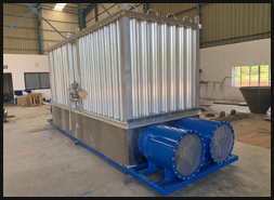
A series of water heated shell and tube vaporizers designed specifically for high or medium rates and continuous duty when operating, for distribution, project and plant back up applications utilizing an external steam source to provide the energy for vaporization or regasification of the stored liquid cryogen.
Steam under pressure is released into treated water stored in a large volume horizontal tank, or a medium volume vertical tank, heating it to the desired operating temperature, and the cryogen is vaporized through a tube bundle or a coil by direct contact with the hot water.
Capacities range from 500 to 85,000 Nm3/hr and units are suitable for all atmospheric gases, LNG, Ammonia and CO2. Common applications include pipeline back-up service, steel plants and other metal processing plants, ceramic plants, breweries, petrochemical and purging applications.
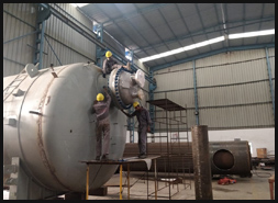
Tube bundles and coils are most commonly manufactured from Stainless Steel and are available in standard metric incremental sizes and are designed and manufactured to the required design pressure, in accordance with the ASME Section VIII Div. 1 code and carry the U stamp. Water storage tanks are most commonly manufactured from carbon Steel in accordance with the ASME code, but do not carry the U stamp. They are painted internally and externally to prevent corrosion. Tank insulation is provided as an option. Bundles and tanks are used in a variety of combinations to provide a cost effective design to meet normal customer requirements of steady state capacity and ballast time. Multiple process and pressure building bundles can be installed in a single tank.
Indirect steam released water bath vaporizers, offer several advantages. The water stored in the tank provides the energy for process gas vaporization to continue even after the loss of the steam supply. This so-called “ballast” time is normally specified by the customer, especially for back-up systems. Typical ballast time is 3 to 5 minutes for this design. Ballast times up to 30 minutes are available, sometimes a requirement for high volume plant back-up systems.
Controls on these units are very simple, and the actual gas discharge temperature is not controlled directly. It relies on the bundle design and the water bath temperature. The steam control valve operates to maintain the water bath temperature. The process bundles are designed to operate effectively within a range of water bath temperatures, depending upon the required ballast time. Indirectly heated systems are more effective than directly heated vaporizers, for providing gas discharge temperatures within reasonable limits.
If low flow conditions are experienced while using a direct steam unit, the resulting gas discharge temperatures can approach the condensing temperature of the steam (1200C to 1500C or higher). The water bath temperature is adjustable, and gas exit temperatures cannot exceed water bath temperature, so gas exit temperatures are easily limited. Control valves actuated by a temperature probe sensing the tank water temperature which in turn activates the steam valve train controls.
The same temperature and pressure limitations that apply to cast iron valves and components in general steam applications, apply to the steam control valves in these units. The use of high temperature/high pressure steam should always be treated with caution.
INDIRECT GAS FIRED WATER BATH VAPORIZERS
HORIZONTAL CONFIGURATION HIGH FLOW RATE UNITS
A series of water heated shell and tube vaporizers designed specifically for high flow rates and continuous duty when operating, for distribution, project and plant back up applications utilizing an internal burner generated hot gas source to provide the energy for vaporization or regasification of the stored liquid cryogen.
The hot gas is circulated within the large volume water tank through heat exchangers, heating it to the desired operating temperature, and the cryogen is vaporized through a tube bundle by direct contact with the hot water.
Capacities range from 7000 to 85,000 Nm3/hr and units are suitable for all atmospheric gases, LNG, Ammonia and CO2. Common applications include pipeline back-up service, steel plants and other metal processing plants, ceramic plants, breweries, petrochemical and purging applications.
Tube bundles and coils are most commonly manufactured from Stainless Steel and are available in standard metric incremental sizes and are designed and manufactured to the required design pressure, in accordance with the ASME Section VIII Div. 1 code and carry the U stamp. Water storage tanks are most commonly manufactured from carbon Steel in accordance with the ASME code, but do not carry the U stamp. They are painted internally and externally to prevent corrosion. Tank insulation is provided as an option. Bundles and tanks are used in a variety of combinations to provide a cost effective design to meet normal customer requirements of steady state capacity and ballast time. Multiple process and pressure building bundles can be installed in a single tank. These systems are basically self-contained and once connected to necessary services, fuel gas and cryogen, are ready for operation.
Indirect hot gas fired water bath vaporizers, offer several advantages. The water stored in the tank provides the energy for process gas vaporization to continue even after the loss of the steam supply. This so-called “ballast” time is normally specified by the customer, especially for back-up systems. Typical ballast time is 3 to 5 minutes for this design. Ballast times up to 30 minutes are available, sometimes a requirement for high volume plant back-up systems
Control of the actual gas exit temperature on these units is relatively simple, and the actual gas discharge temperature is not controlled directly. It relies on the bundle design and the water bath temperature. The system is controlled by a temperature sensor that senses the tank water temperature and signals the burner(s) electro pneumatic control systems to provide hot gas which circulates through heat exchangers within the tank, before being exhausted to atmosphere.
The process bundles are designed to operate effectively within a range of water bath temperatures, depending upon the required ballast time. Indirectly heated systems are more effective than directly heated vaporizers, for providing gas discharge temperatures within reasonable limits.
A burner housing is built onto the end of the water storage tank, and the cryogen process tube bundle(s) and pressure building tube bundle(s) are located at the opposite end. The burner housing is designed to accommodate twin 50% or 100% operation burners to enable systems to be provided with the burner redundancy specified by the project.
WATER CIRCULATING VAPORIZERS
DIRECT WATER CONTACT VAPORIZERS
HORIZONTAL CONFIGURATION MEDIUM - HIGH FLOW RATE UNITS
A series of water heated shell and tube vaporizers designed specifically for medium to high flow rates in which an externally supplied hot water source is circulated through the shell and the cryogen is vaporized or re-gasified in the tube bundle, and is used for distribution, project and plant back up applications.
Direct water heated vaporizers are a very simple solution to cost effective cryogen vaporization providing an external source of hot water is available. Performance is directly related to the temperature of the water source. They are extremely simple to operate. This series of vaporizers can be used either as part of a water circulating vaporizing ‘system’ in which an external water heater is also provided or as a stand-alone vaporizer where the customer provides the water, usually sourced from an existing water heating process or hot water that has to normally pass through a cooling water circuit.
Vaporizers can operate in vertical or horizontal configuration. Capacity is dependent upon shell side water temperatures. Water circulating vaporizers are perfect if the gas outlet temperature is sensitive and the process cannot accept elevated exit gas temperatures. The use of a water heated vaporizer, guarantees the exit gas temperature can never exceed the incoming water supply temperature.
Water circulation vaporizers are self-controlling and do not require any external, expensive flow control devices, temperature monitors or control devices. It is the ultimate, reliable, cost effective, economic solution for simple gas vaporization. The design matches the flow rate of the available water to the required maximum vaporization heat load, ensuring full vaporization of the incoming cryogen with a reasonable gas exit temperature. The water flow rate becomes a fixed parameter simplifying the operating controls. Even if the cryogen flow reduces, full vaporization is achieved and the gas exit temperature approaches closer to the incoming water temperature, but still a value acceptable to the process, since it cannot be higher than the water temperature.
Individual heat exchangers are commonly used as a local product vaporizer, especially for CO2 vaporization in Breweries and bottling plants and also for disposal vaporizers for air separation plants, and are frequently used in back-up service.
Control systems are not generally included in individual water heated vaporizers, but are available if required. Standard safety system options are also available, comprising a low water flow switch, a low water temperature switch, and a low gas temperature switch all connected to an automatic process inlet valve. If any of the preset conditions are not met, the process inlet valve will shut off the cryogen flow protecting the heat exchanger from damage from ice build-up. The safety system is beneficial for any system, but particularly those operating with cooler water supplies.
ELECTRIC VAPORIZERS
A series of electrically heated vaporizers and trim heaters designed specifically for medium to high flow rates utilizing standard electrical power. Units are available for use with all industrial gases such as Oxygen, Nitrogen, Argon, LNG, Ammonia and Carbon Dioxide CO2 as well as other specialized and exotic gases.
These new vaporizers have significantly improved features as compared to previous cast block or modular plate designs. The heater elements are easily removable and replaceable without affecting the integrity of the vaporizer construction. Low pressure drops are attainable along with effective hear transfer rates. The units are lightweight, portable and require a smaller footprint than comparable models.
These electric cryogen vaporizers utilize high quality electric immersion type heating elements and multiple stainless steel heat exchanger coils connected between low pressure header assemblies. The electric immersion heating elements and the gas tubes are specially positioned in a highly conductive fluid inside an atmospheric pressure vertical tank. Heat transfer is further enhanced within the vaporizer coils by means of gas turbulence devices within each stainless steel cryogen coil, which eases and prevent slug flow and fluid surging.
The vaporizer electrical control design comprises a solid state temperature controller, independent auto resetting over temperature switch controller and a separate manual resetting high limit shutdown controller. Controls are all housed in a dust proof rubber gasketed electrical enclosure with an interlocked handle. Individual electrical components are U.L. recognized, CSA certified and IEC approved, and units can be manufactured in accordance with European regulations and carry the CE mark. Units are available in multiple voltages. Power requirements may vary slightly with each specific voltage. Options available are low temperature shut off valve; Polyurethane painted NEMA 4 or Stainless Steel enclosures; ANSI, DIN or Mueller four-bolt flanged connections.
Standard atmospheric gas models are available with flow rates from 19Nm3/hr to 800Nm3/hr.
Power requirements available from 5kW up to 100kW.
Standard models for Carbon Dioxide CO2 are available with flow rates from 32kg/hr to 900kg/hr.
Power requirements available from 5kW up to 100kW.
Standard maximum working pressure 580 psig (40barg)
Pressures up to 10,000 psig (690barg) available
Our Products
- Hot Water Bath Vaporizers
- Fuel Or Steam Heated Vaporizers
- Dual Gas NH3/N2 Vaporizer
- GROFE Cryogenic Pumps & Valves
- Cryogenic Tank
- Ambient Vaporizer
- Forced Draft Vaporizer
- Pressure Building Coils
- LNG Vaporizer
- Purging Vaporizers
- LIN/ LOX/ LAR/ LNG Switching Systems
- Electrical Vaporizers
- Direct Steam Heated Vaporizers
- Other Products
Industry We Serve
- Steel
- Oil & Gas
- Medical
- Automobile
- Food & Beverages
- Electronic
- Pharmaceutical
- Energy
- Offshore
- Glass
- Tyre